Polish
 English
 German
 Swedish
 Spanish
 Eastern Region


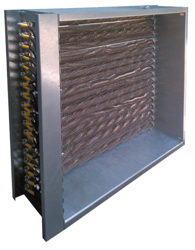
 Return to main menu


Our products worldwide
Algeria, Austria, Finland, Georgia, Kazakhstan, Latvia, Lithuania, Morocco, Moldova, Romania, Ukraine, Switzerland, Serbia, Bulgaria, Belgium, Cyprus, Czech Republic, Denmark, England, Greece, Hungary, Ireland, Mexico, Mongolia, Netherlands, Slovakia, Slovenia, Sweden, France, Finland, Portugal, Spain, Estonia, Norway, Egypt, Croatia, Canada, Germany, Italy, United Arab Emirates, Singapore, United States, Libya